This is a continuation of copending application Ser. No. 07/093,474 filed on Sept. 4, 1987, now abandoned.
BACKGROUND OF THE INVENTION
1. Field of the Invention
The invention relates generally to the field of digital data processing systems and more specifically to communications mechanisms for facilitating communications among nodes in a system employing multiple nodes.
2. Description of the Prior Art
In the past, digital data processing systems, or computers, were large and expensive systems including one or only a few central processor units connected to a main memory, mass storage such as disk and tape units, and input/output units such as printers, video display terminals, and telecommunication links. Because of the cost of such systems, they typically supported a number of users, and a significant amount of design effort went into making them faster. However, as more parts of the computers were put onto integrated circuit chips, including entire central processor units, the cost of computers declined dramatically, and so it became cost effective in many applications to devote a single computer to one or only a few users.
A benefit of having all users using a single large computer system is that data and programs may be shared among a number of users. This benefit can also be realized in an environment of smaller computers if they are linked together, for example, to form a distributed system. In a distributed system, the system is controlled by a host computer which provides services to the smaller computers, which are termed "nodes", such as data and program sharing, scheduling of resources such as printers, backup storage, and the like.
A problem arises, however, in facilitating communications among nodes, that is, in allowing nodes to initiate transfers of information, comprising data and programs, to and from other nodes. In the past, information transfers were asymmetric, that is, the host generated commands, which were performed by the nodes, and the nodes generated responses. In such systems, the host maintained a set of queues for each node, each queue including a command queue, a response queue and a message queue. The host loaded commands into the command queue and the node processed each command and inserted a response into the response queue. If the node required service from the host, but not in response to a command, it loaded a message into the message queue. The host received the message and provided the required service. The information was actually transferred in buffers which were unique to each node and not accessible to the other nodes. If a node required an information transfer with another node, the initiating node essentially had to request the host to perform the transfer, which pre-empted the host from performing other operations.
SUMMARY OF THE INVENTION
The invention provides a new and improved communications mechanism for facilitating communications among diverse nodes connected to a host in a heterogeneous distributed digital data processing system.
In brief summary, the communications mechanism includes a common queue buffer which is used to contain message queues for all of the nodes in the system. To perform an information transfer, a node inserts a message into an entry into the queue of the receiving node. If the message indicates a transfer of data, it also identifies the location of a buffer containing the data. Upon retrieving the queue entry from its queue, the receiving node may retrieve the contents of the buffer. The queue buffer is identified by a common descriptor block which is accessible by all of the nodes in the system.
BRIEF DESCRIPTION OF THE DRAWINGS
This invention is pointed out with particularity in the appended claims. The above and further advantages of this invention may be better understood by referring to the following description taken in conjunction with the accompanying drawings, in which:
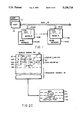
FIG. 1 is a general block diagram of a digital data processing system incorporating a communications mechanism in accordance with the invention;
FIGS. 2A through 2C are data structures used in connection with the communications mechanism;
FIGS. 3A-3E depict details of control and status registers used in connection with the communications mechanism; and
FIGS. 4A-1, 4A-2, 4B-1, 4B-2 depict flow diagrams detailing the operations of the new communications mechanism.
DETAILED DESCRIPTION OF AN ILLUSTRATIVE EMBODIMENT
1. General Description
FIG. 1 depicts a general block diagram of a digital data processing system incorporating a communications mechanism in accordance with the invention. With reference to FIG. 1, the digital data processing system includes a host 10 and a plurality of nodes 11(0) through 11(N) (generally identified by reference numeral 11) interconnected by a bus 12. As is conventional, the host includes a host processor (not shown) with an associated host memory 13 which serve to initialize and provide services to the nodes 11. The nodes 11 may also include processors, intelligent mass data storage subsystems, network adapters and the like. At least some of the nodes may have an associated node memory 14(0) through 14(N) (generally identified by reference numeral 14). Each node 11 also has a set of communications control and status registers 15(0) through 15(N) (generally identified by reference numeral 15). The contents of each set of control and status registers 15 are described below in connection with FIG. 3.
As is conventional, the host memory 13 may be accessed by a host processor (not shown), and it may also be accessed by the nodes 11 by read or write information transfers over bus 12. That is, words of information may be written to, or read from, the host memory 13 by the host processor, and words of information may also be written to or read from the host memory 13 by the nodes 11. (A word is the number of bits of information, typically sixteen, thirty two or sixty four bits, which may be transferred over the bus 12 at one time.) In addition, in one specific embodiment, at least some of the node memories 14 can be accessed, by means of transfers over bus 12, by nodes 11 other than the node 11 with which each is associated. In initiating the transfer of a word of information over the bus 12 the initiating unit transmits an address over the bus. The range of addresses which may be transmitted over bus 12 defines a physical address space which identifies locations in the host memory 13 and in the node memories 14 which may be accessed over bus 12. In one embodiment, each of the nodes 11 and the host 10 is also identified by a node identification number which is used in connection with transfers over bus 12.
The communications mechanism in accordance with the invention facilitates transfers of blocks o information among nodes 11 over bus 12. Each block comprises one or more individual words of information. Before proceeding further with a description of the operation of the communications mechanism, it would be helpful to first describe the various data structures which are used in connection with the communications mechanism and the various communications control and status registers 15. The data structures are described in Part 2 below in connection with FIGS. 2A through 2C and the communications control and status registers 15 are described in Part 3 below in connection with FIG. 3.
2. Data Structures
The communications mechanism includes several data structures, which are depicted in FIGS. 2A through 2C, and which are maintained by the host 10 in the host memory 13. In particular, the host 10 maintains in host memory 13 a system descriptor block 20, shown in detail in FIG. 2A, which contains information as to the locations, in host memory 13, of a queue buffer 21, which will be described below in connection with FIGS. 2B and 2C. The host 10 identifies the location of the system descriptor block 20 in host memory 13 by loading the address of the base of the system descriptor block 20 into the communications control and status registers 15 in the nodes 11 on initialization. Thereafter, as described below, the nodes 11 may access information in the system descriptor block 20 over bus 12, and based on the information retrieved therefrom, access the queue buffer 21.
A. System Descriptor Block 20 (FIG. 2A)
With reference to FIG. 2A, the system descriptor block 20 comprises a header 30 and a plurality of node entries 31(0) through 31(N) (generally identified by reference numeral 31) each associated with one of the nodes 11(0) through 11(N). The header 30 includes a number of fields. As noted above, the system descriptor block 20 identifies the location in host memory 13 of the queue buffer 21; this information is maintained in a queue buffer base address field 32 and a queue buffer length field 33.
The queue buffer base address field 32 is a pointer to the base of the queue buffer 21. That is, the queue buffer base address field 32 contains the address of the base of the queue buffer 21. The queue buffer length field 33 contains a value which identifies the length of the queue buffer 21. Together, the queue buffer base address field 32 and the queue buffer length field 33 form a queue buffer descriptor.
The system descriptor block header 30 also contains a queue entry length field 34. As described below in connection with FIG. 2B, the queue buffer 21 includes a plurality of queue entries, all of which have the same length and the queue entry length field 34 identifies the length of an individual queue entry.
The header 30 of the system descriptor block 20 also includes several housekeeping fields. A system descriptor block length field 35 identifies the length of the system descriptor block 20 in host memory 13. A version number field 36 identifies a version number of the communications mechanism. As noted above, in one embodiment, the host has an associated node identification number, which is stored in a host node identification field 37 in the system descriptor block 20. In addition, in one embodiment, programs use conventional virtual addresses which are translated into physical addresses for transfers over bus 12. Fields 40 and 41 of the system descriptor block 20 contain the physical address and virtual address, respectively, of the system descriptor block 20, specifically of the base of the system descriptor block 20, which corresponds to field 35. The nodes 11 may use the contents of fields 40 and 41 to verify that the system descriptor block 20 is properly loaded in host memory 13; an error may be noted by the nodes 11 to the host 10 if the translated contents of virtual address field 41 do not correspond to the contents of the physical address field 40.
The fields in the various node entries 31 are all the same (although the contents of the fields in the node entries 31 may differ), and so the fields of only node entry 31(0) will be described in detail. As described below in connection with FIG. 2B, the queue buffer 21 maintains one or more free queues, and the node entry 31 includes a free queue number field 42 which contains a value that identifies the number of free queues and a free queue index field 43 which contains a value which will be described below in connection with FIG. 2B.
In addition, in the embodiment in which programs use virtual addresses, a node entry 31 contains a system page table descriptor 45 and a global page table descriptor 46. The system page table descriptor 45 contains two fields, one containing the base address and the other the length of the system page table. The system page table contains information for translating certain virtual addresses, most particularly those relating to processing of operating system programs, into physical addresses. The global page table descriptor 46 also contains two fields, one for the base address and the other for the length, of the global page table, which is used to facilitate sharing of information among programs.
B. Queue Buffer 21 (FIGS. 2B and 2C)
The queue buffer 21 is used by each of the nodes 11 to transmit to the other nodes messages, which may include data transfer commands and responses, as described below. The queue buffer 21 effectively maintains, in one buffer, separate queues for each of the nodes 11 and one or more free queues. The free queue is a source of queue entries which may be appended by the nodes 11 to their respective queues as described below.
The queue buffer 21 comprises a queue buffer header 50 at the beginning of the buffer followed by a queue buffer body 51 which contains a plurality of queue entries 56(0) through 56(M) (generally identified by reference numeral 56). The queue buffer header 50 comprises a plurality of queue headers 52(0) through 52(N) (generally identified by reference numeral 52) each associated with one of the nodes 11 and a free queue header 53 for each free queue. Each node 11 uses the queue header 52 which corresponds to the node's node number in the system depicted on FIG. 1.
FIG. 2B depicts a queue buffer 21 having one free queue and one free queue header 53. If the queue buffer 21 has more than one free queue, the queue buffer header 50 has one free queue header 53 for each free queue. Each queue header 52 and 53 in the queue buffer 21 comprises two entries, namely, a forward link, generally identified by reference numeral 54, and a backward link, generally identified by reference numeral 55. FIG. 2B depicts in detail the forward link 54(0) and backward link 55(0) for queue (0) header 52(0).
As described above in connection with the system descriptor block 20 in FIG. 2A, each node entry 31 includes a free queue number field 42 and a free queue index field 43. The contents of the free queue number field 42 generally identifies the number of free queues and the contents of the free queue index field 43 generally identifies number of queue headers in queue buffer header 50 preceding the first free queue header 53 so as to thereby identify the first free queue header 53 in the queue buffer header 50. Alternatively, the contents of the free queue index field 43 identifies the first free queue header 53 which the node 11 is to use and the free queue number field 52 identifies the number of free queues which the node 11 may use.
As will be described below in connection with FIG. 2C, each of the queue entries 56 in the queue buffer body also includes queue link information including a queue forward link field and a queue backward link field. The contents of the forward link field 54 in a queue header 52 or 53 points to a queue entry 56 in queue body 51 which is the first entry in the queue associated with that queue header 52 or 53. The contents of the forward link field in the first queue entry 56 points to the queue entry 56 which is the next entry in the queue, and so on. The contents of the queue backward link field in each queue entry points to the preceding entry in the queue, and the contents of the queue backward link field 55 in a queue header 52 or 53 points to the last entry in the queue associated with the queue header 52 or 53. The pointers in the forward link field 54 and backward link field 55 in the queue headers 52 and 53 and in the queue entries 56 may be either addresses or offsets from the base of the queue buffer 21.
The operations performed by the nodes 11 in manipulating the queues defined by the queue headers 52 and 53, and of linking queue entries to the various queues will be described below in connection with a description of the operation of the communications mechanism.
The detailed structure of each queue entry 56 is depicted in FIG. 2C. With reference to FIG. 2C, each queue entry 56 begins with the entry's queue link 60, which includes the forward link field 61 and backward link field 62. Following the queue link is a command/response field 63 which, in turn includes four fields, namely, a status field 64, a type field 65, a source field 66 and a destination field 67. The status field 64 indicates success or failure of the message transfer. The contents of the type field 65 identifies the type of command, that is, the direction of transfer of the message. The contents of the source field 66 and destination field 67 identify, by node number, the source and destination, respectively of the message. It will be appreciated that the source or destination of a message may be either a node 11 or the host 10.
Following the command/response field 63 is a length field, which indicates the length of a message packet 70 which follows in the queue entry 56. The contents of a message packet depends on the particular message being transmitted. FIG. 2C depicts the structure of a message packet 70 which may be used in connection with transfer of data between the source node and destination node (that is, the source or destination of the message packet 70 contained in the queue entry 56). In that case, the message packet includes a message field 71 indicating the direction of transfer of the data, that is, from the source node to the destination node or from the destination node to the source node.
A flags field 72 in the message packet 70 contains various flags relating to the transfer. A length field 73 identifies the amount of data to be transferred, and a buffer pointer field 74 identifies the location of the buffer which either contains the data, if the data transfer is to be from the message source to the message destination, or which is to receive the data if the data transfer is to be from the message destination to the message source. In one embodiment which uses virtual addresses, the flags field 72 may be used to indicate whether the contents of the buffer pointer 74 is a pointer to the buffer to be used in the data transfer, or a pointer to a buffer which, in turn, contains pointers to buffers to be used in the data transfer.
Alternatively, a message packet 70 which responds to the data transfer message described above may just include a message field indicating the receipt of the data and a flags field 72 indicating whether the data was properly transferred. In that case, the type field 65 indicates the success or failure of a message transfer, and the flags field 72 indicates the success or failure of the data transfer.
3. Communications Control And Status Registers
Each node 11 and the host 10 has a set of five communications control and status registers 15 which are used by the nodes 11 and host 10 to control communications. Each set of communications control and status registers 15 in a node 11 can be accessed directly by the corresponding node 11 and by the other nodes 11 and host 10 by conventional data transfers over bus 12. The communications control and status registers 15 in host 10 are accessible by all of the nodes 11. The five communications control and status registers 15 include a control register 100, an attention register 107, a status register 101, a data register 102 and an error register 103.
The control register 100 includes a single field for receiving a command from host 10. In one embodiment, the host 10 may issue commands to initialize the node 11 and allow it to begin message transfers, to stop transfers, to restart transfers, and to control access to the status register 101 and data register 102.
The attention register 107 includes a single field for receiving the identification of a node 11 or the host 10. If a queue in queue buffer 21 associated with a node 11 is empty, and then another node 11 or the host 10 inserts a queue entry 56 into the queue, the unit inserting the queue entry into the queue enters a value into the attention register 107 which corresponds to its node identification on bus 12. Similarly, if a queue in queue buffer 21 associated with the host 10 is empty and a node 11 inserts a queue entry 56 into the queue, the node 11 enters a value into the attention register 107 which corresponds to its node identification on bus 12. In either case, when a value is written into the attention register of a node 11 or the host 10, the node 11 or host 10 is interrupted to begin retrieving queue entries 56 from its queue as described below.
The status register 101 includes an update flag 110, which is used to synchronize access to the status register 101 by the node 11 and the host 10, a data flag 105 whose condition indicates whether the node 11 may use the contents of the data register 102, and a node status field 112 whose contents indicate the node's status, such as, for example, whether it has been initialized, whether an error has occurred, whether it attempted to obtain a queue entry 56 (FIG. 2B) from the free queue but the free queue was empty, and so forth. The status register update flag 110, when set by the node 11, indicates that the status register 101 has been updated. The status register update flag 110 is cleared by the host 10 when it retrieves the contents of the status register 101 and loads a command in the control register 100 indicating that it has retrieved the contents of the status register 101.
The host 10 uses the data register 102 to provide the base address of the system descriptor block 20 (FIG. 2A) to the node 11. Prior to initializing the node, the host 10 loads a command in the control register which reserves to it the use of the data register 102. In response to the command the node 11 sets the data flag 105. Thereafter, the host writes the base address of the system descriptor block 20 into the data register 102 and loads an initialization command in the control register 100. In response, the node initializes and clears the data flag 105.
The node 11 uses the error register 103 to report errors to the host 10. When an error occurs, the node 11 inserts an error code into the error register 103, provides an appropriate entry in the node status field 112 of the status register 101 if a command has been received from the host 10 allowing the node to update the status register 101, and sets the status register update flag 110. Thereafter the node 11 may transmit a conventional interrupt request over bus 12 to obtain service from the host 10, or the host 10 may poll to determine that the status register 101 has been updated.
4. Operation
With this background, the operation of the communications mechanism will be described in connection with FIGS. 4A-1 through 4B-2. Preliminarily, to initiate operations over the communications mechanism, the host 10 first establishes the various data structures, including the system descriptor block 20 (FIG. 2A) and queue buffer 21 (FIG. 2B). In addition, the host 10 loads the base address of the system descriptor block 20 into the data registers 102 of the nodes 11 and loads initialization commands in their control registers 100 (FIG. 3) to enable them to start operating. Thereafter, the nodes 11 may communicate by transferring messages through the queues in queue buffer 21, which may relate, as noted above, to transfers of data in buffers defined in the messages.
FIGS. 4A-1 and 4A-2 detail operations in inserting messages in queue entries 56 in the queues maintained in the queue buffer 21. This may occur following insertion of data into a buffer as described below, and so it will be assumed that the node 11 has been initialized and activated.
Initially, the node 11 which performs the insertion, identified in FIGS. 4A-1 and 4A-2 as node A, has the identification of both the source and destination nodes. With reference to FIG. 4A-1, node A first uses the base address of the system descriptor block 20 to initiate retrieval of the contents of the queue buffer base address field 32, the queue buffer length field 33 and the queue entry length field 34 in the system descriptor block 20 (step 170). In addition, node A retrieves the contents of the free queue number field 42 and the free queue index field 43 from the node entry 31 associated with the node 11 whose queue is to receive the command or response, which is identified as node B.
Node A then retrieves node B's queue header 52 and the queue header 53 of the free queue. The free queue supplies an empty queue entry which 56 node A links to node B's queue and into which node A inserts the command or response. Specifically, using the base address of the queue buffer 21 from queue buffer base address field 32 and node B's identification, node A then retrieves the contents of node B's queue header 52 (step 171). Node B's node identification essentially forms an index into the queue buffer header 50 which node A uses to identify node B's queue header 52.
Using the queue buffer base address and the contents of the free queue index 43 which node A retrieved (in step 170) from node B's node entry 31, node A then retrieves the free queue header 53 (step 172) and determines if it has any queue entries 56 (step 173). In one embodiment, a queue is empty, that is, it has no queue entries 56 if both the backward link 54 and forward link 55 in its header 53 are zero. If the free queue is empty, and if the contents of the free queue number field 42 retrieved from node B's node entry 31 identifies one free queue, node A sequences to step 174 to indicate an error, as described above (step 174).
If in step 173 a free queue is identified which is not empty, node A sequences to step 175 to load a message into the first queue entry 56 in the free queue (step 175). The first queue entry 56 is the queue entry 56 pointed to by the forward link 54 in the free queue header 53. Node A, after determining from the contents of node B's queue header whether node B's queue is empty, then proceeds to link the queue entry 56 to the tail of node B's queue by conditioning node B's queue header 52, the free queue header 53, and the appropriate queue links in the various queue entries 56 to link the queue entry 56 (step 176).
In particular, since the queue entry 56 is being removed from the head of the free queue, the forward link 54 of the free queue header 53 must be modified to point to the second queue entry (which, after removal of the first free queue entry for linkage to node B's queue, will be the first queue entry 56 in the free queue). The backward link 62 of the queue link of the second queue entry 56 in the free queue must also be modified to point to the free queue header 53. In addition, if the queue entry 56 is being linked at the tail end of node B's queue, the forward link 61 of the queue entry 56 which was previously at the tail end of node B's queue (or the forward link 54 of the queue header 52 if node B's queue was empty) must be modified to point to the new queue entry 56. In addition, the backward link 55 of the queue header 52 must be modified to point to the new last queue entry 56. Finally, the queue link 60 of the queue entry 56 being linked to node B's queue must be modified. Specifically, the forward link 61 of the new queue entry 56 must be modified to point to node B's queue header 52, and its backward link 62 must be modified to point to the queue entry 56 which was previously at the tail end of the queue, and which was previously identified by the backward link 55 of node B's queue header.
After the new queue entry 56 is linked into node B's queue in step 176, node A sequences to step 177 (FIG. 4A-2), in which it determines whether node B's queue was empty prior to step 176. If it was empty, that is, if node A inserted a queue entry 56 into a previously empty queue, node A loads a value into node B's attention register 107 thereby interrupting node B and, as described below in connection with FIGS. 4B-1 and 4B-2, enabling it to retrieve the new queue entry 56 from its queue (step 178). After conditioning node B's queue entry 56, it exits the insertion routine depicted in FIGS. 4A-1 and 4A-2 (step 179). If node B's was not previously empty, node A sequences directly to step 179 to exit.
As described above in connection with FIGS. 4A-1 and 4A-2, if node A conditions node B's attention register 107 (FIG. 3) in node B's communications control and status registers 15 after inserting a queue entry onto node B's queue, node B, if previously initialized, begins retrieving queue entries from its queue and processing them. If node B's queue was not empty when node A inserted a queue entry on node B's queue, node A does not condition node B's attention register, but node B, in iteratively retrieving and processing queue entries from its queue, will, unless previously stopped by a command loaded by host 10 in its control register 100, eventually retrieve and process the queue entry inserted by node A onto its queue. In either case, node B performs the sequence depicted in FIGS. 4B-1 and 4B-2 to retrieve and process the queue entry 56. With reference to FIG. 4B-1, node B first verifies that the host has initialized it so that it is operating over the communications facility (step 190). If not, node B waits until it is initialized. When node B is finally initialized, it sequences to step 191 in which it tests the attention register 107 in its communications control and status registers 15. If a value has not been loaded into the attention register, node B returns to step 190.
If, in step 191, the node attention register 107 contains a non-zero value, node B accesses its queue to retrieve a queue entry 56 for processing. Node B sequences to step 192 in which it uses the base address of the system descriptor block 20, which is in its data register 102, to retrieve the contents of the queue buffer base address field 32, the queue buffer length field 33 and the queue entry length field 34. In addition, node B retrieves the contents of the free queue number field 42 and free queue index field 43 in its node entry 31 in the system descriptor block 20.
Using the retrieved contents of the queue buffer base address field 32 and its node identification, node B then retrieves the contents of its queue header 52 from queue buffer header 50 (step 193). Node B then tests the contents of forward link 54 and backward link 55 to determine if the are both zero, in which case node B's queue is empty (step 194). If node B determines that its queue is empty, it returns to step 190 (FIG. 4B-1).
If, on the other hand, node B determines in step 194 that its queue is not empty, it sequences to step 197, in which it retrieves the contents of the queue entry 56 which is pointed to by the queue forward link 54 in its queue header 52, that is, the first queue entry 56 in its queue. Node B then links the queue entry 56 to the free queue (step 200). In this operation, node B performs operations similar to those described above in connection with step 176. Node B sequences to step 203 to process the message retrieved from the queue entry 56.
After node B processes the message retrieved in the queue entry 56 (step 203), it sequences to step 204 in which it determines whether the host 10 has loaded a command in its control register 100 enabling it to stop using the communications facility. If not, it tests its queue header 52 to determine if its queue is empty (step 205). If node B determines that its queue is not empty, it sequences to step 192 to retrieve and process the next queue entry 56. If node B determines in step 205 that its queue is empty, it sequences to step 190 to wait for another node 11 to load its attention register 107 indicating insertion of a queue entry 56 into its queue.
As noted above, the communications facility can be used to transfer message among diverse heterogeneous processors for many purposes. For example, the messages can be used to enable transfers of data among nodes 11 and host 10. In particular, if a node 11 or host 10 wishes to transmit data, it may create a buffer, load data into it, generate a message packet 70 (FIG. 2C) indicating the data transfer in message field 71 and location and size of the buffer in fields 72 through 74, and insert it into a queue entry 56 and link the queue entry into the queue in queue buffer 21 associated with the intended recipient as described above.
In addition, if a node 11 or host 10 wishes to enable another to transmit data to it, it generates an appropriate message packet 70 and inserts it into a queue entry and links the queue entry 56 into the appropriate queue in queue buffer 21 as described above. The other unit, either a node 11 or host 10, when it processes the queue entry 56, inserts data into a buffer, which may, but need not be, defined in the message packet which initiated the operation, and generates a message packet comprising a response. If the initiating message packet did not identify the buffer to be loaded with the data, the response message packet does identify the buffer, and the node 11 or host 10 receiving the response message packet may retrieve the data from the buffer.
It will be appreciated that, since the host 10 is also a node on bus 12, it may also communicate with the nodes 11 through the communications mechanism described above. In particular, since host 10 has a node identification number, it has a node entry 31 in system descriptor block 20 and a queue header 52 in queue buffer 21. Accordingly, the host 10 may transmit messages to, and receive them from, nodes 11 through the queues in the queue buffer 21.
It will also be appreciated that the communications mechanism provides efficient information transfer between nodes 11 without requiring any significant participation by host 10 after it initializes the data structures depicted in FIGS. 2A through 2C, other than in connection with handling of error recovery operations. Thus, the communications mechanism leaves the host 10 free to do other processing while the nodes 11 engage in information transfer.
The foregoing description has been limited to a specific embodiment of this invention. It will be apparent, however, that variations and modifications may be made to the invention, with the attainment of some or all of the advantages of the invention. Therefore, it is the object of the appended claims to cover all such variations and modifications as come within the true spirit and scope of the invention.